First response today. The switch outputs for the TR relays are the two sets of contacts 1, 4, 3 and 8,9, 11.
For the equipment’s relays T1 and T2 the switch output is 5,6 (and maybe 7).
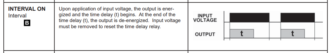
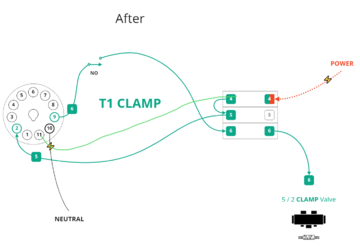
The triggering for T1 and T2 is caused by the application of mains power across 2 and 10. When this happens the timer function of T1/T2 starts and results in the closing of the T1/T2 internal contacts connected between their 5 and 6 terminals. By applying mains Line to terminal 5 a device can be switched according to the timer function by connecting it to 6 and Neutral.
In summary for now 5, 6 on T1/T2 are not trigger inputs as they are for the TR series of relays you show function and terminal diagrams for.
If the timer function of T1/T2 is triggered by power applied to 2 and 10, then we could use one of the TR series and rejig the wiring to its base so that it performs just like a T2/T2. The switching - what you mean by output would done using one triplet 1, 4, 3 or 8, 9, 11 with a Line being connected to 3 or 11 and the load to 3 or 9 respectively.
What remains to be clarified is the timer function actually required so that the TR operates like the T1/T2. This is what we need to know next. I suggest the use of the neon lamps so the timer function can we watched. My earlier post refers.
Note well- as the panel is currently wired you cannot use any of the TR relays because your panel uses 5 and 6 as contacts to switch mains power whereas the TR relays uses them as input start timer function triggers.