Discuss Cable Size Query in the Solar PV Forum | Solar Panels Forum area at ElectriciansForums.net

Welcome to ElectriciansForums.net - The American Electrical Advice Forum
Head straight to the main forums to chat by click here:   American Electrical Advice Forum

Reaction score
0
Hello, I'm hoping someone can help me with a problem I've come across on behalf of a colleague.
A single phase PV system with a 6kW inverter has its AC running 187m underground to its point of termination. The cable that has been used is a run of 3 core SWA (6mm) carrying the neutral, and another cable of the same 6mm, 3 core SWA carrying the positive. The installer claims this effectively makes it a 2 core 18mm cable.
Would that be fit for purpose with the voltage drop over that distance (I gather 5% is acceptable loss?).
I've tried cable calculators online, but they default to the standard cable sizes either side of 18mm (16 & 25).
Thanks in advance to any of those that can help.
 
For all practical purposes, the voltage drop of an 18mm² cable will be 8/9 of the tabulated drop for 16mm², which for two single-core cables on single-phase AC is 2.8mV per amp per metre.
2.8 x 8/9 = 2.5mV/A/m
Drop for 6kW at 230V:
2.5 x 187 x 6000/230 = 12.2V
12.2 / 230 = 0.053
Therefore the maximum drop is just a shade over 5%

But there seems to be another problem, which is that single-core SWA cables (and a 3-core cable with its cores paralleled is electrically a single-core cable) are not suitable for AC. With a multicore cable the line and neutral cores are contained within the same armour, carrying equal currents in opposite directions, therefore their magnetic fields cancel out and do not induce currents in the steel armour. But with single-cores separately armoured, the armour of both cables lies between the current in one direction and that in the other, the current effectively flowing in a loop around the steel, causing eddy-current heating and longitudinal voltages in the armour. The solution for normal single-core cables is to use aluminium armour, but presumably these are indeed steel as you say.

I don't personally have any experience of the degree of practical effect and the kind of current at which it becomes serious (although in any case it is non-compliant.) Perhaps someone else has met it in real life?
 
The eddy current problem in the swa steel armour could be reduced if one swa cable carried LLN and the other NNL.

Whether this is a BS compliant way of using SWA for electrical installations I would not know. Of course the conductors would have to be carefully sleeved up and a notice provided at each end of the run.

The eddy current would then be reduced to a 1/3 of the present situation. Like Lucien I have no experience to say whether this is a problem.

My worry would not so much be the heating effect but unexpected potential difference across the ends of a break in the SWA loop if it were to happen. With my scheme this too would be reduced to a third. Again, I'd place some notice at either end.

Perhaps make call to an SWA cable maker?

AEI Cables - Setting the standards | Home - http://www.aeicables.co.uk/
[automerge]1601525695[/automerge]
The power of Ohmic heating effect of the smaller induced eddy current would be reduced to a ninth of what it is now - in my view not a problem to the cables.
[automerge]1601527116[/automerge]
Using the idea of energy conservation, the maximum power that could ever be dissipated in the swa armour wires is that available from the 6kW inverter. If it were all to be dissipated as Ohmic heating of the swa - clearly it would not be - the linear heating effect is 6000/(2 x 187) = 6000/380 = 16Watts/metre.

This is easily dissipated by a the 3 core 6mm2 swa cable.

With my scheme the linear power dissipation would reduce to 16/9 = just under 2Watts/metre - trivial.

The heating effect of the eddy current is not a problem.
 
Last edited:
Hysteresis and eddy-current ohmic dissipation won't be a problem as far as cable operation is concerned, I agree, but they might be an unacceptable extra energy loss and / or the end-end voltage of a run with the armours insulated might not have been taken care of.

I was also going to mention LLN and NNL, but decided there was little point in suggesting a method prohibited by BS7671. Thinking about it again, 521.5.2 specifically prohibits single-core cables, which LLN and NNL are not, although clearly the intent is to avoid residual current through ferrous armour so this would be more a case of dodging the reg rather than complying with it.

The longitudinal voltage could be cancelled out by changing the permutation of cores mid-run, where they must pass through a suitably-prepared junction box. That would just leave the magnetic losses.
 
Frisbee-Dave: Could you re-locate the inverter to the other end of the cable run and send instead the dc current from the solar array to it along the two swa cables configured as (+ -) and (+ -) in parallel with one conductor in each cable unused? What is the maximum dc voltage of the pv array? SWA rated 600/1000V rms ac is rated for 1500Vdc - but you'd need to confirm for your swa cable.

myCableEngineering.com > Voltage - https://mycableengineering.com/knowledge-base/voltage

For dc current flows in swa there are no longitudinal induced voltages/currents, no eddy currents nor hysteresis effects in the armouring. Arranging positive and negative conductors as (+ -) within the swa means the magnetic fields around them both nigh on cancel out. If the pv array voltage is significantly greater than 230V there would also be lower IsquaredR end to end power loss where I is the dc current of the array.

Putting the inverter closer to the supply intake also reduces the risk of inverter ac over voltage fault/disconnection when generating peak ac power and a high grid voltage pertaining at the same time.

Food for thought.
 
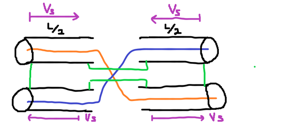
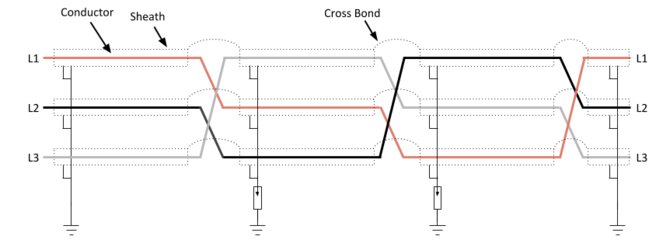
By way of a teach-in, the scheme Lucien mentioned to cancel out the induced voltage in the armouring is often called 'bonding and transposition' which is especially important on long, high voltage, high current single conductor armoured cable.

For the single phase case the idea is as shown in my first attachment. The sum of the induced voltages in the four equal length section is nigh on zero - clever eh.

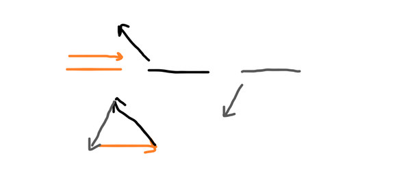
For three phase power transfer along three single conductor armoured cables the scheme looks like the second image. This time the induced voltages along each 'horizontal' level is arranged by the transposition of conductors between equal length section to sum to zero - the classic delta sum of equal magnitude phasors displaced in phase by 120 degrees. The two boxes with a single arrow inside are SVL - Sheath Voltage Limiters - see:

EM Electrical Material & Contracting - http://www.emelec.com.tr/page/product-detail/9/sheath-voltage-limiters
[automerge]1601727021[/automerge]
Frisbee-Dave - I am not suggesting you adopt this scheme. I should have made that clear in my earlier previous post.
 

Attachments

  • Cable Size Query sheathvoltage - EletriciansForums.net
    sheathvoltage.png
    26.2 KB · Views: 4
  • Cable Size Query crosstranspose - EletriciansForums.net
    crosstranspose.png
    15.4 KB · Views: 4
  • Cable Size Query delta - EletriciansForums.net
    delta.png
    12.5 KB · Views: 2
Last edited:

Reply to Cable Size Query in the Solar PV Forum | Solar Panels Forum area at ElectriciansForums.net

OFFICIAL SPONSORS

Electrical Goods - Electrical Tools - Brand Names Electrician Courses Green Electrical Goods PCB Way Electrical Goods - Electrical Tools - Brand Names Pushfit Wire Connectors Electric Underfloor Heating Electrician Courses
These Official Forum Sponsors May Provide Discounts to Regular Forum Members - If you would like to sponsor us then CLICK HERE and post a thread with who you are, and we'll send you some stats etc
This website was designed, optimised and is hosted by Untold Media. Operating under the name Untold Media since 2001.
Back
Top
AdBlock Detected

We get it, advertisements are annoying!

Sure, ad-blocking software does a great job at blocking ads, but it also blocks useful features of our website. For the best site experience please disable your AdBlocker.

I've Disabled AdBlock