Discuss Motors in the Canada area at ElectriciansForums.net

Re: Primary resistance starter

Primary resistance starter

I’ve only ever seen two of these, they were used on lift motors.

As you can see from the drawing they are pretty simple. On start up contactor K2 closes allowing a reduced voltage to the stator windings, after a short time delay contactor K1 closes and K2 drops out.
They suffer from being limited to X number of starts per hour due to heat build up.

View attachment 14202

View attachment 14201

Is this not just effectively a liquid starter?

Any advantage to this design?
 
Liquid starters are normally used on slip ring motors where isolation of the phases isn’t as important. There’s no reason a liquid starter couldn’t be used as a primary resistance but it would need major re-engineering to make it safe. Instead of one earthed tank for the electrolyte, three separate insulated tanks would be needed. There was a company in the 70/80’s that made Statormatic starters, the same company made Vapormatic starters for slip-ring motors.
View attachment 14208
Slip ring rotor
View attachment 14207
Stator
 
Delt with a lot of liquid starters at the cement plant I used to work, usually with 3.3kv drives, had a few long days when the brush gear flashed over with carbon dust, we did try to blow them oh weekly but production often superseded maintenance.

I was just thinking about the therory behind it, am I right in thinking a star delta starter would be a cheeper way of setting this up? I take it the resistor bank is used for the same reason the liquid starters are used? Never seen that set up before.
 
The primary resistance has the beauty that it’s flexible as to the % of torque at start up. Star/delta is 1/√3 only.

The beauty of a slip ring motor is it’s high starting torque, something you wouldn’t get with start/delta. A cement mill would just sit there and not move in star. On top of that even at √3 of the DOL starting current (say 6X FLC/√3 = 3.46X FLC) the 3.3 OCB would trip on instantaneous overload. The cement mills I’ve worked on ranged from 900 to 6000HP, I wouldn’t like to be around when the breaker opened. I was stood in front of a 3.3 ACB when that tripped due to a slip-ring flashover, I near had to go and change my underpants.
For heavy starting loads you can’t beat slip-ring motors.

Some I’ve worked on were variable speed using the Kramer system. They started using a liquid starter. Once at full speed the Kramer control would kick in and regulate the current in the rotor, the recovered energy being fed back in to the 11KV system via an inverter and step up transformer.
View attachment 14214
 
We had a system very similar to that tuning one of the kiln firing fans, it was an abb multidrive invertor 2Mva, that used a resistor bank to start and also managed to recover energy from the drive.

Never got my head around how that worked, it was only on site a couple of months before I left. Was delivered in a steel container as a plug and play system, it weighed 27tonnes.
 
The ones we had for the ID fans were about 20 years old. I had one of the thyristor packs fail, I was near it when it went. When we opened the panel we were expecting a charred mess but no the only thing was a blown fuse. That is what I’d heard. Changed the fuse and it’s thyristor pack and it ran perfectly afterwards.

The fuse went in spectacular style, the thyristor tested perfectly?

View attachment 14226View attachment 14227
 
Hi tony, on one of our sites we are running the supply fans for cooling at 120% and 45% above the working Limit of the supply fuses and thyristor. Every 2-3 months we have to replace the lot. Occasionally the supply cable melts and that gets changed as well.... Oh and the cab door is fully open as to keep temp down :)

Madness but cheaper than upgrading the whole system.......
 
Yes, costs us approx 200-300 for replacement parts, (fuses we change more regular weekly)

Upgrade the system for additional capacity and improved running efficiency = £5.4million

We are upgrading in the next 12 months as part of the phase 3 improvements which will see data storage at the site increased by 40% and power increase from grid upped to silly levels.

Nedl currently pulling new 300mm Hv supply cables in directly from the sub station 15 miles away. With a secondary supply coming in from another site. That's costing £15million alone.

So until then we have to live with repairs!!! Lol
 
Kramer speed control

This is a somewhat bizarre method of controlling the speed of a slip-ring motor. I’ve worked on them up to 2500HP, RoB2, has I think worked on bigger drives.

View attachment 14587
The motor starts as a normal motor using the liquid starter. Contactors 1 and 3 close and the motor runs up to speed using the liquid starter. Once at full speed the shorting contactor 2 closes.
The motor can then work like this or the speed can be controlled. For speed control contactor 4 closes and the inverter synchronises to the transformer. Contactor 2 and 3 then open, all the current from the slip-rings is then fed via the inverter and transformer to the incoming supply. Slowing the speed raises the ring voltage at the same time reducing the current. Reducing the current allows the slip of the motor to increase thus slowing it. This excess power feeds back in to the supply. I’ve watched one of the 2500HP (1865KW) feeding back up to 750KW in to the system.
The transformer has a six phase primary Star and Delta with a delta secondary DSd.
These are now superceded by MV VSD’s. these come with their own headaches such as 11KV water cooled inverters.

View attachment 14588View attachment 14589
This fuse was out of a Kramer drive. It near gave me heart failure when it blew, but the drive just carried on as if nothing had happened!
 
Last edited by a moderator:
There now all nicely packed into one plug and play 27tonne inverter. No liquid starter needed. Massive air conditioning units needed fitting though it chucked some heat out.

Ill try and dig some photos of it, not sure if I ever took any.


5FAF71CF-798E-4E9A-9BB5-909DFAF3BA64-19366-000012BC5AC9298F.jpg


When using them to power more than one drive, the regenerated power is shared along a dc bus, because
It runs at near unity power factor, it's pretty efficient.
 
So a little on DC drives for a wet Sunday afternoon.

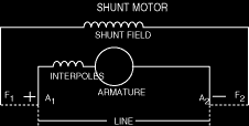
Shunt-Wound Motors - This type of motor runs practically constant speed, regardless of the load. It is the type generally used in commercial practice and is usually recommended where starting conditions are not usually severs. Speed of the shunt-wound motors may be regulated in two ways: first, by inserting resistance in series with the armature, thus decreasing speed: and second, by inserting resistance in the field circuit, the speed will vary with each change in load: in the latter, the speeds is practically constant for any setting of the controller. This latter is the most generally used for adjustable-speed service, as in the case of machine tools.
ShuntMotor.gif


The shunt motor is probably the most common dc motor used in industry today. Components of the shunt motor are the armature, labeled A1 and A2, and the field, labeled F1 and F2. The coils in the shunt field are composed of many turns of small wire, resulting in low shunt field current and moderate armature current. This motor provides starting torque that varies with the load applied and good speed regulation by controlling the shunt field voltage. If the shunt motor loses it’s field it will accelerate slightly until CEMF rises to a value sufficient to shut off the torque producing current. In other words, the shunt motor will not destroy itself if it loses its field, but it won’t have the torque required to do the job it was designed for.
Some of the common uses of the shunt motor are machine shop lathes, and industry process lines where speed and tension control are critical.

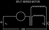
Series-Wound DC Motors - This type of motor speed varies automatically with the load, increasing as the load decreases. Use of series motor is generally limited to case where a heavy power demand is necessary to bring the machine up to speed, as in the case of certain elevator and hoist installations, for steelcars, etc. Series-wound motors should never be used where the motor cab be started without load, since they will race to a dangerous degree.
SplitSeriesmotor.gif


Seriesmotor.gif


Components of a series motor include the armature, labeled A1 and A2, and the field, S1 and S2. The same current is impressed upon the armature and the series field. The coils in the series field are made of a few turns of large gauge wire, to facilitate large current flow. This provides high starting torque, approximately 2 ¼ times the rated load torque. Series motor armatures are usually lap wound. Lap windings are good for high current, low voltage applications because they have additional parallel paths for current flow. Series motors have very poor speed control, running slowly with heavy loads and quickly with light loads. A series motor should never drive machines with a belt. If the belt breaks, the load would be removed and cause the motor to over speed and destroy itself in a matter of seconds.
Common uses of the series motor include crane hoists, where large heavy loads will be raised and lowered and bridge and trolley drives on large overhead cranes. The series motor provides the starting torque required for moving large loads. Traction motors used to drive trains are series motors that provide the required torque and horsepower to get massive amounts of weight moving

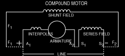
Compound-Wound DC Motors - A combination of the shunt wound and series wound types combines the characteristics of both. Characteristics may be varied by varying the combination of the two windings. These motors are generally used where severe starting conditions are met and constant speed is required at the same time
Compoundmotor.gif


When comparing the advantages of the series and shunt motors, the series motor has greater torque capabilities while the shunt motor has more constant and controllable speed over various loads. These two desirable characteristics can be found in the same motor by placing both a series field and shunt field winding on the same pole. Thus, we have the compound motor.
The compound motor responds better to heavy load changes than a shunt motor because of the increased current through the series field coils. This boosts the field strength, providing added torque and speeds.
If a shunt coil is added to a series motor at light loads (when a series motor tends to over speed) the added shunt field flux limits the top speed, eliminating self-destruction.
Common uses of the compound motor include elevators, air compressors, conveyors, presses and shears. Compound motors can be operated as shunt motors by disconnecting the series field. Many manufacturing process lines are designed this way. The reason being that, most off the shelf motors are compound motors, and the series field can always be connected later to provide additional torque, if needed.
Compound motors can be connected two ways, cumulatively and differentially. When connected cumulatively, the series field is connected to aid the shunt field, providing faster response than a straight shunt motor. When connected differentially, the series field opposes the shunt field. Differentially connected compound motors are sometimes referred to as “suicide motors,” because of their penchant for self destruction. If perhaps, the shunt field circuit were to suddenly open during loading, the series field would then assume control and the polarity of all fields would reverse. This results in the motor stopping, and then restarting in the opposite direction. It then operates as an unloaded series motor and will destroy itself. Differentially connected motors can also start in the opposite direction if the load is too heavy. Therefore, it is seldom used in industry
 
Designs, Patents and Copyright Act 1988.

The simple reason all drawings have been removed is purely down to the current situation on certain boards. Any drawings I post in future on any board (both UK or international) will be held on a hosting site. This is to protect my rights under the Designs, Patents and Copyright Act 1988.
To restrict access to copyright material both written and illustrative infringes both the Designs, Patents and Copyright Act 1988 and the Data Protection Act.
 

Reply to Motors in the Canada area at ElectriciansForums.net

Similar Threads

Hi, I am looking for a connection diagram or sugestions for a 2.2Kw single phase motor to drive a compressor. The spec plate shows that it can be...
Replies
5
Views
770
Friend of mines dryer machine has stopped working, 2 days out of warranty. I am trying to help theme out as money is tight for them however, I'm...
Replies
1
Views
643
Looking for counsel / guidance to replace an original Dayton On/off with speed control switch. I’ve checked with a couple local electrical supply...
Replies
5
Views
703
I need to connect a replacement motor for a septic tank agitator. I've identified that the motor needs to be connected to a 4mf run capacitor but...
Replies
2
Views
679
Hi I'm in a bit of a pickle trying to set up my hot water and central heating systems. Got a gas boiler with a pressure tank and a motor...
Replies
7
Views
873

OFFICIAL SPONSORS

Electrical Goods - Electrical Tools - Brand Names Electrician Courses Green Electrical Goods PCB Way Electrical Goods - Electrical Tools - Brand Names Pushfit Wire Connectors Electric Underfloor Heating Electrician Courses
These Official Forum Sponsors May Provide Discounts to Regular Forum Members - If you would like to sponsor us then CLICK HERE and post a thread with who you are, and we'll send you some stats etc
This website was designed, optimised and is hosted by Untold Media. Operating under the name Untold Media since 2001.
Back
Top
AdBlock Detected

We get it, advertisements are annoying!

Sure, ad-blocking software does a great job at blocking ads, but it also blocks useful features of our website. For the best site experience please disable your AdBlocker.

I've Disabled AdBlock