- Reaction score
- 3,569
Last week I did a job for forum member joramtor. Link to the original post here: http://www.electriciansforums.co.uk...s-your-area/87967-repair-micc-pyro-cable.html
He had an underground mineral cable that had been severed by the groundworkers so off we went to sort it out for him. The length of cable that was broken was about 50m long and ran between two lamp posts in his driveway. I thought I might put up some photos of the work along with an explanation so that those less experienced with mineral might learn something. Feel free to add to it if you want (I'm sure much flaw picking and critisism will ensue also ).
).
First off the customer snipped a piece off and posted it to me so that I could determine whether it was imperial or metric and also so that I could size the pots and glands needed if it was imperial (the job was over an hour away so couldn't just pop round). Upon receiving it it was immediately apparent that it was imperial so I used my calipers to size the pots and glands needed. The pots needed were 2L2.5, the glands needed were 4L1.5 and the seals needed were 4L1. The cable in question was 4 core with the conductors being equivalent to 0.75mm-1mm.
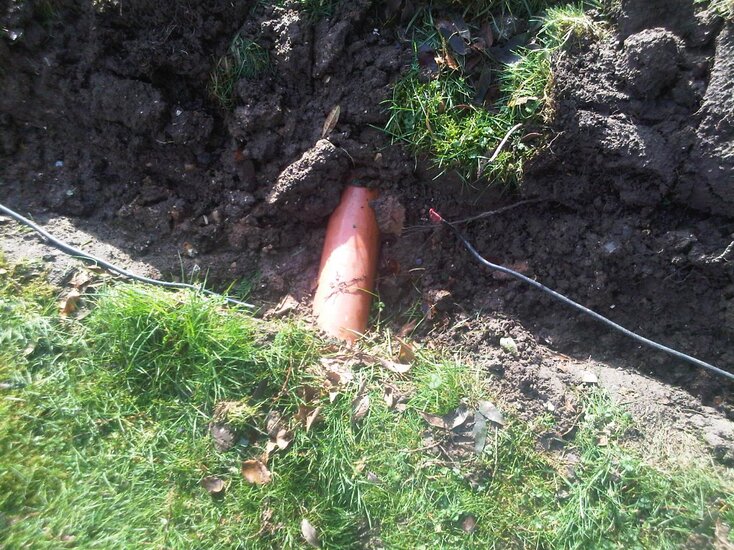
When I arrived at the job this is what I found, it had been lying here like this, exposed, for about four months:
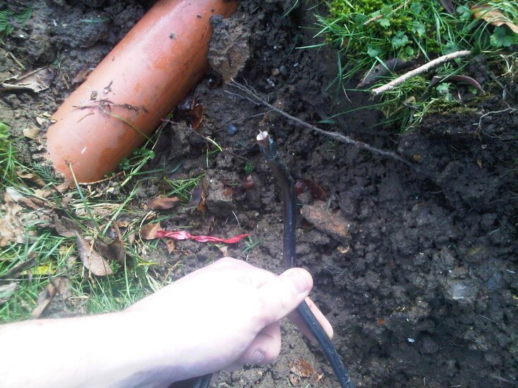
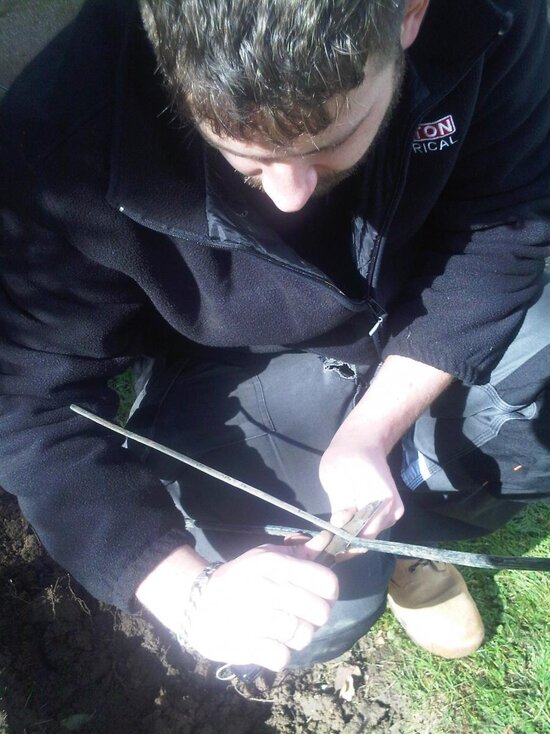
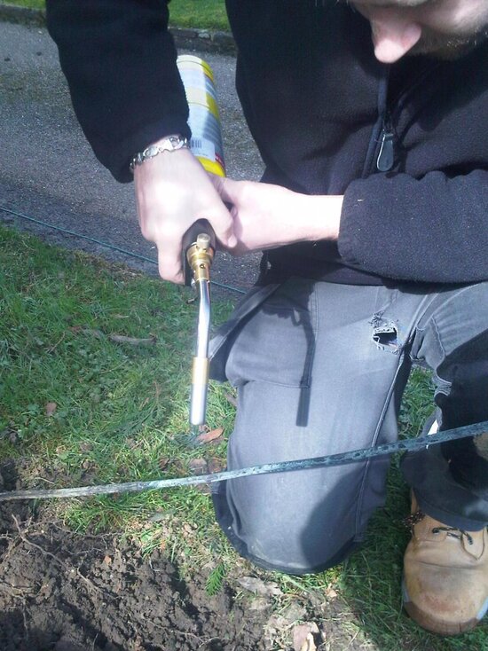
First thing's first, isolate and lock off (circuit was already off at the breaker). Then to start... I chopped the ends away with an angle grinder for a neat and square application of the stripper (a square end always makes starting off the stripper easier) and stripped back a good three quaters of a meter of the sheath with a ring and pull. Next thing to do is to get the blowtorch out and give the cable a good blasting. Short, slow even strokes towards the cut end of the cable from about 650mm back to get rid of any moisture ingress. Remember the magnesium oxide that makes up the insulating mineral compound is hygroscopic, it wicks up moisture like nobody's business! So we have to get that out.
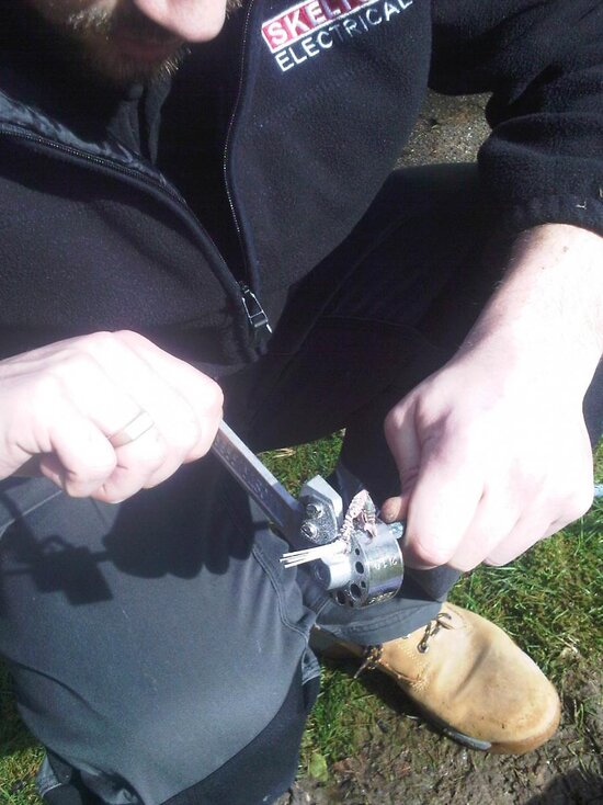
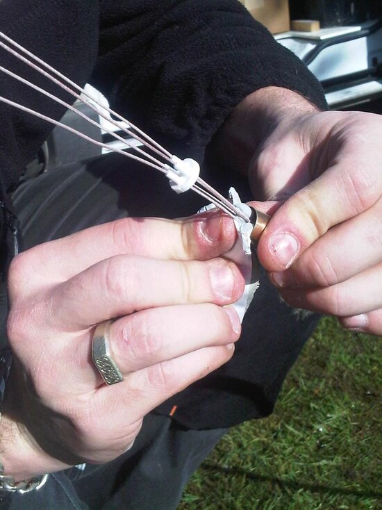
After ten or so minutes of doing this I let the cable cool and after it was, I slid on the glands and then started stripping it back with the joistripper. This was tougher than usual as the cable was very slightly too fat to fit in the 2L2.5 hole and a bit loose in the 4L1.5 hole. I went through two blades with this bit! In hindsight I should really have used a heavy duty stripper but hey ho. When the cables were stripped back the pots were screwed on and potting compound was applied from one side only to eliminate air pockets within the pot. Notice the caps are half slid down, this helps to keep the conductors in place through the potting compound filling process. The caps were then put in place and crimped using a mineral crimping tool.
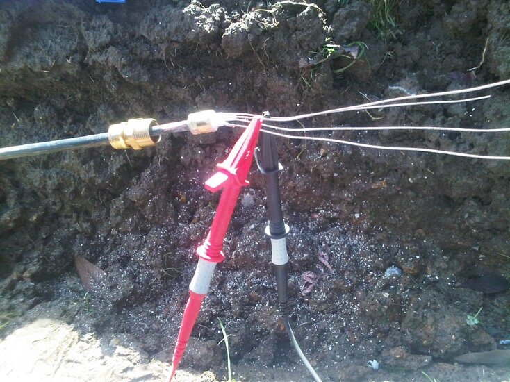
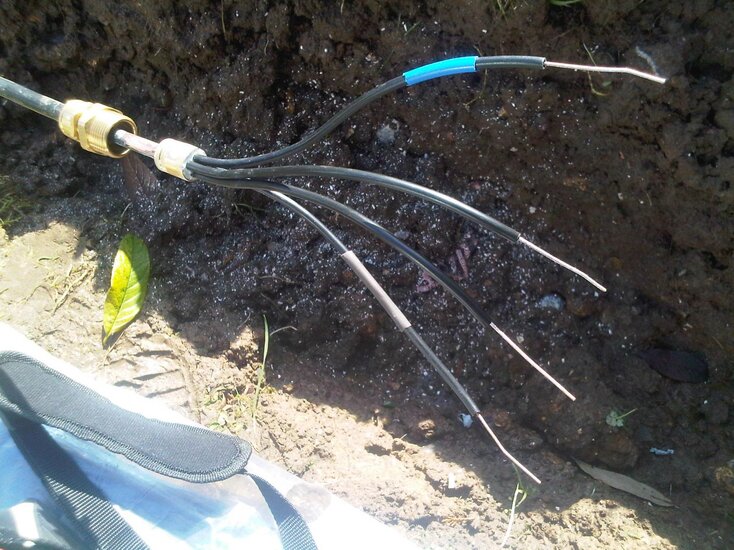
When this was done it was time to IR the conductors and copper sheath. The lowest result was roughly 20Mohms live-live. Not perfect but okay. After this I belled out the ends between the break and each lamp post with my long lead to determine which core was which and also to check earth continuity on the sheath which was being used as the cpc. Once this was done the insulation was applied and the cables identified. Two cores were not used and were disconnected at the lamp posts. At the supply end I ensured that these were earthed as they previously weren't.
Once this was done I terminated the gland at one of two Pratley underground junction boxes making sure to clean the copper on the exposed mineral sheath to ensure zero resistance between this and the olive within the compression gland. I then prepared a short length of 4 core 1mm SWA to bridge the gap and terminated this into the other side of the Pratley.
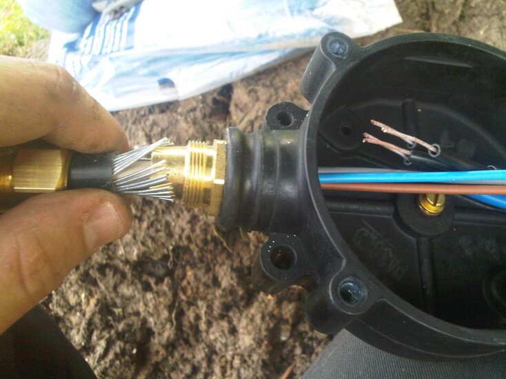
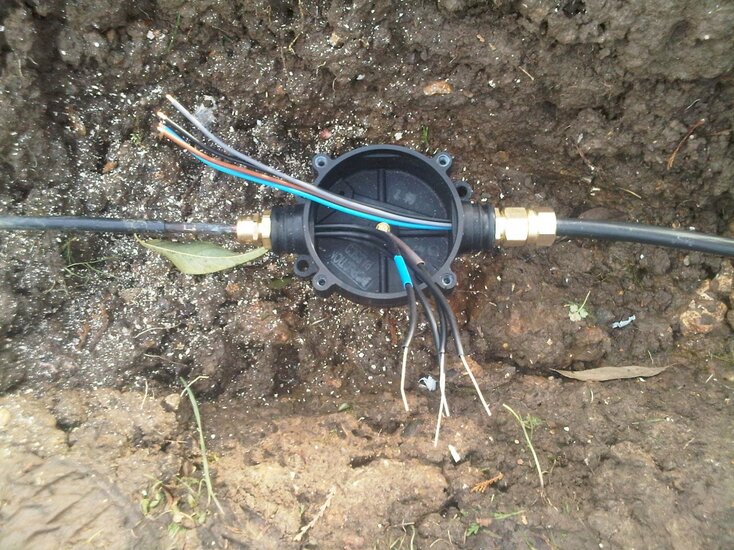
This process was then repeated on the second Prately on the other end of mineral cable so that the short length of SWA was the bridge in the gap of the break. Once this was done it was time to seal the gland terminations. I tightly wrapped some insulation tape at the join between the glands and the cable to ease the transition and then wrapped tightly and carefully with a couple of layers of self amalgamating tape. This will seal the joins and prevent corrosion of any previously exposed metal.
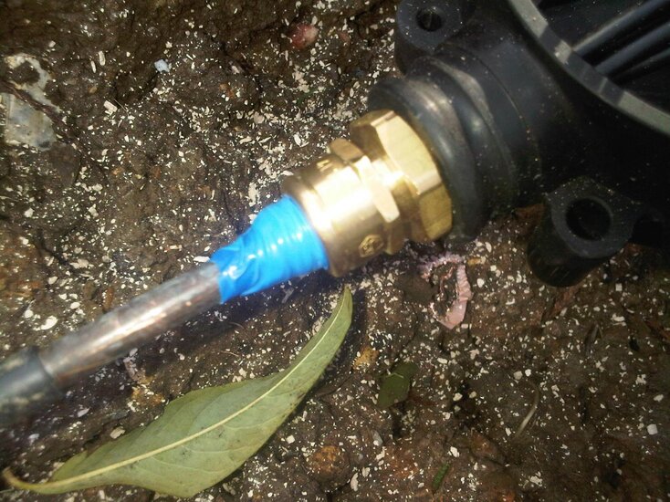
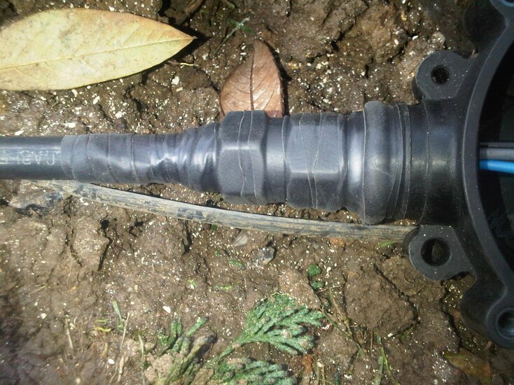
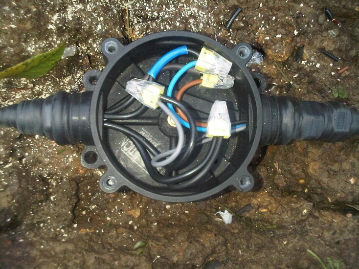
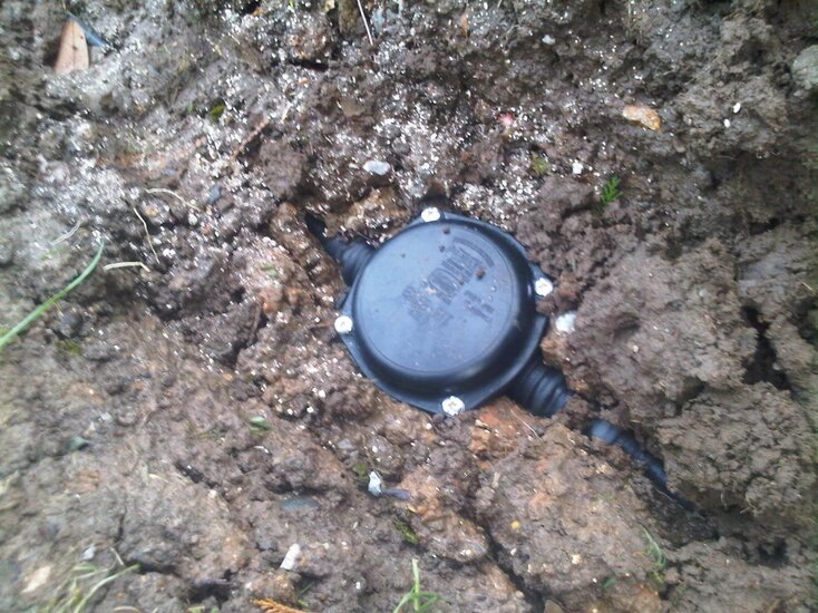
Once sealed up the cables were joined with wagos and the circuit tested, dead tests then live. Total lowest IR had now reduced to 15Mohms (a product of the increase in length [2x25m = 50m]), again, not perfect but okay. Pratleys have a built in method of preserving cpc continuity so no need for fly leads. All tested out ok so MCB on and a functional test of the circuit carried out. All ok. MCB off, JBs sealed up with the lids and put in place, circuit energised and away we go!
The customer was told by more than one person that it couldn't be done, and here it is! Never say never!
He had an underground mineral cable that had been severed by the groundworkers so off we went to sort it out for him. The length of cable that was broken was about 50m long and ran between two lamp posts in his driveway. I thought I might put up some photos of the work along with an explanation so that those less experienced with mineral might learn something. Feel free to add to it if you want (I'm sure much flaw picking and critisism will ensue also
First off the customer snipped a piece off and posted it to me so that I could determine whether it was imperial or metric and also so that I could size the pots and glands needed if it was imperial (the job was over an hour away so couldn't just pop round). Upon receiving it it was immediately apparent that it was imperial so I used my calipers to size the pots and glands needed. The pots needed were 2L2.5, the glands needed were 4L1.5 and the seals needed were 4L1. The cable in question was 4 core with the conductors being equivalent to 0.75mm-1mm.
When I arrived at the job this is what I found, it had been lying here like this, exposed, for about four months:


First thing's first, isolate and lock off (circuit was already off at the breaker). Then to start... I chopped the ends away with an angle grinder for a neat and square application of the stripper (a square end always makes starting off the stripper easier) and stripped back a good three quaters of a meter of the sheath with a ring and pull. Next thing to do is to get the blowtorch out and give the cable a good blasting. Short, slow even strokes towards the cut end of the cable from about 650mm back to get rid of any moisture ingress. Remember the magnesium oxide that makes up the insulating mineral compound is hygroscopic, it wicks up moisture like nobody's business! So we have to get that out.


After ten or so minutes of doing this I let the cable cool and after it was, I slid on the glands and then started stripping it back with the joistripper. This was tougher than usual as the cable was very slightly too fat to fit in the 2L2.5 hole and a bit loose in the 4L1.5 hole. I went through two blades with this bit! In hindsight I should really have used a heavy duty stripper but hey ho. When the cables were stripped back the pots were screwed on and potting compound was applied from one side only to eliminate air pockets within the pot. Notice the caps are half slid down, this helps to keep the conductors in place through the potting compound filling process. The caps were then put in place and crimped using a mineral crimping tool.


When this was done it was time to IR the conductors and copper sheath. The lowest result was roughly 20Mohms live-live. Not perfect but okay. After this I belled out the ends between the break and each lamp post with my long lead to determine which core was which and also to check earth continuity on the sheath which was being used as the cpc. Once this was done the insulation was applied and the cables identified. Two cores were not used and were disconnected at the lamp posts. At the supply end I ensured that these were earthed as they previously weren't.


Once this was done I terminated the gland at one of two Pratley underground junction boxes making sure to clean the copper on the exposed mineral sheath to ensure zero resistance between this and the olive within the compression gland. I then prepared a short length of 4 core 1mm SWA to bridge the gap and terminated this into the other side of the Pratley.


This process was then repeated on the second Prately on the other end of mineral cable so that the short length of SWA was the bridge in the gap of the break. Once this was done it was time to seal the gland terminations. I tightly wrapped some insulation tape at the join between the glands and the cable to ease the transition and then wrapped tightly and carefully with a couple of layers of self amalgamating tape. This will seal the joins and prevent corrosion of any previously exposed metal.


Once sealed up the cables were joined with wagos and the circuit tested, dead tests then live. Total lowest IR had now reduced to 15Mohms (a product of the increase in length [2x25m = 50m]), again, not perfect but okay. Pratleys have a built in method of preserving cpc continuity so no need for fly leads. All tested out ok so MCB on and a functional test of the circuit carried out. All ok. MCB off, JBs sealed up with the lids and put in place, circuit energised and away we go!


The customer was told by more than one person that it couldn't be done, and here it is! Never say never!


