M

murd_the_nerd

Hi there

Complete novice electrical wise. I am refurbishing an old 1950s Injection Moulding machine and looking to replace the Power Timer Relays. So far with no success myself and two attempts. It appears I need some expert help. I would love direction on the type of timer I need and a link to where I could purchase is a bonus. Any help much appreciated. Details below:
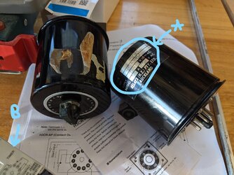
The old Timers:
1645685277155.png


What I've investigated:
  • There are 2x Timers, one for inject and one for clamp
  • They are both the same, because I can swap them around and it still runs just fine
  • Markings still remaining on one says Supply 230 V AC and Rating 6A 230 V AC. There is no cut down in power on this machine, 240V throughout.
  • They appear to be short-circuit driven (not power on all the time and Start commands etc)
  • Power is only supplied when they run and is instantly straight through to the output
  • 11 pin circular configuration
  • Phase to pin 2, Neutral to pin 10
  • Power into pin 5 and 2 makes the output run forever until short-circuited. I think I've heard this called an Inhibit function which allows the Timer to pause and force power through pin 6. In the clamp instance this forces the clamp closed, lets the inject sequence run, and then allows the Timer to run before cutting power and releasing the clamp.
  • Pin 6 is the only output. This runs to the 5/2 solenoid valves and changes the valve position for either inject or clamp
  • Timer appears to be a Power Off Delay or similar as it only tells it when to cut power off

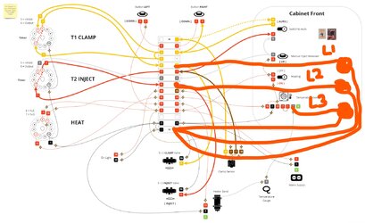
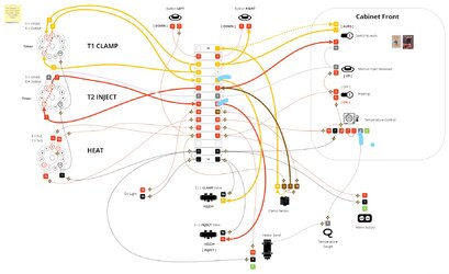
Diagrams that I've mapped to help explain how the Timers work and current wiring:
1645685398265.png


1645685420357.png


If you need any more info I'm happy to provide. And even if you are just interested in the machine I can post pictures of that also :)

Thanks
Murdoch
 
Interesting... will take a closer look later. Might be a silly question but if the relays work, why are you replacing them?

I am not sure what you mean by 'short-circuited' as far as the output is concerned. I would read that as a short between line and neutral that would blow the fuse, but clearly you mean something else. Can you please clarify...
 
  • Like
Reactions: murd_the_nerd
This sounds like one that might interest Lucien!
Relays and timers, etc that use this style of plug in base are still available today, but to preserve originality, you're probably going to have to carefully open up the faulty one and see what the problem is. If beyond repair, there's plenty of room to fit a modern replacement inside the can an seal it up again'

Edit: I see I was right! Lucien has replied while I was typing this.
Thanks brianmoooore, yes I've seen Lucien has replied so hope they can help :) I've tried two 11pin new timers and failed so getting the right one is the challenge
 
Interesting... will take a closer look later. Might be a silly question but if the relays work, why are you replacing them?

I am not sure what you mean by 'short-circuited' as far as the output is concerned. I would read that as a short between line and neutral that would blow the fuse, but clearly you mean something else. Can you please clarify...
Hi Lucien

Thanks for replying. Yes they do actually still work and I can run the machine through a full sequence. Unfortunately the dials and knobs and internals are all a bit knackered. So each time I come back to the machine it has vibrated and the dials moved around or if I tighten too hard it goes past and spins the case. So in short, repeatability so that when I get molds I can simply set it to 2 for example and it is 2 :)

Sorry I'm not fully up on the electrical lingo (a designer myself). But basically I'm trying to describe that there isn't power to these timers all the time like more modern versions of the 11pin. The modern ones appear to have power all the time and then trigger a start sequence. Where as these old ones appear to just get up and running once the power is applied to either 2 or 2 and 5. Then outside of itself in the sequence it is tripped and power disconnected. Does that make sense?

The two timers I have tried and failed with are:
H3CR-A (knock off version of this link below)

TR-6162U

Here's a look inside the cabinet:
1645745394264.png


And machine if of interest:
1645745455553.png
 
Could you tell us what is stamped on the plate circled A? See attachment.

Circled at B are the connections to pins of a device; which one? Could you show these too if they refer to the relay you wish to source new?
 

Attachments

  • timerrelaysnz.jpg
    timerrelaysnz.jpg
    1.8 MB · Views: 62
  • Like
Reactions: murd_the_nerd
Could you tell us what is stamped on the plate circled A? See attachment.

Circled at B are the connections to pins of a device; which one? Could you show these too if they refer to the relay you wish to source new?
Hi Marconi

Sure, here is a close up of the stamp and my guesses:

Type: ET P1 TIME
Ref: R1783 0.2-5 SECS
Supply: 230 V50 AC
Rating: 6A 230 V AC

1645832683406.png


And as for some new ones I'm wondering about there are these:

Macromatic Analag Timer TAA2U
1645833130839.png


Autonics AT11EN
1645833303333.png


From my understanding the numbers 3, 4, 8, 9 are internal to the Timer. But where I struggle is, what is considered an Output and Input. Because from the looks I require Input to 5 to inhibit. And then I want 6 as the Output to the solenoid valve. I also see the - and + are the other way around on these timers.

Any help appreciated :)
 
I
Hi Marconi

Sure, here is a close up of the stamp and my guesses:

Type: ET P1 TIME
Ref: R1783 0.2-5 SECS
Supply: 230 V50 AC
Rating: 6A 230 V AC

View attachment 95470

And as for some new ones I'm wondering about there are these:

Macromatic Analag Timer TAA2U
View attachment 95471

Autonics AT11EN
View attachment 95472

From my understanding the numbers 3, 4, 8, 9 are internal to the Timer. But where I struggle is, what is considered an Output and Input. Because from the looks I require Input to 5 to inhibit. And then I want 6 as the Output to the solenoid valve. I also see the - and + are the other way around on these timers.

Any help appreciated :)
I will study these over the weekend. I have found this firm which does a wide range of 11 pin timers both electronic and mechanical. There are others of course. Just need to determine the functionality and pin out to select the correct replacements:

Foxtam Electronic Timers - Foxtam Controls - https://www.foxtamcontrols.co.uk/products/foxtam-electronic-timers?gclid=CjwKCAiAvOeQBhBkEiwAxutUVHSvHPRKJ82h19_XRP_x6cjnG9xgrFnutB03_ZHWCQ_b9qyrUHY_OhoCuRoQAvD_BwE
 
  • Friendly
Reactions: Jim_e_Jib
mud_the _nerd: Do you have a multimeter with an 'Ohms' range? If not could you buy a cheap digital one?

If you look at the attachment you will see two identical tables. The numbers refer to the pins on the relay. Using a multimeter please measure first the resistance between pin 1 and then to each of pins 2 to 11 of the black round timer and enter the meter reading in the table. Then do the same for pin 2 but this time to pin 1 and the each of 3 to 11. Then pin 3 but to 1 then 2 and then each of 4 to11, etcetera.

The first table is for when the timer is set to zero seconds. The second table for when it is set to say 5 seconds.

The resistance between the pins will be a low value apart from I think between pins 2 and 10.

I hope this is clear. Then return the two tables to me as an attachment.
 

Attachments

  • Like
Reactions: murd_the_nerd
Chances are that there is a modern version of what you want available, but it will likely be more sophisticated than the original, with unwanted additional functions built in. These you may have to disable, or ensure that they are not accidentally enabled.
 
  • Like
Reactions: murd_the_nerd
Further to my last post; could you remove the black T1 and the white timer T2 and the heat relay and then take a photo of the wiring to their bases? Also take a clear picture of the terminal block so I can see which wire goes in to which terminal and to where the other ends go on the three relay bases.

Or you could do the wire tracing for me and send me a diagram. Do you have the manual for the machine with its wiring diagram inside?
Thanks so much for looking into this. I don't have a multimeter but I think I will buy one so I can test for you.

I actually stumbled on this article which might shed some light. It looks like timers that old might have been True Off Delay timers rather than more modern Off Delay timers. https://www.macromatic.com/blog/relays/what-is-a-true-off-delay-function

"Upon application of input voltage, the output is energized. When the input voltage is removed, the time delay (t) begins. At the end of the time delay (t), the output is de-energized. Input voltage must be applied for a minimum of 0.1 seconds to assure proper operation. Any application of the input voltage during the time delay (t) will reset the time delay. No external trigger is required."

From a search I can find some 240v 8pin ones of these. But I haven't found a 240v 11pin version. Do you know how I would test to see if a True Off Delay or not?

I do have my own attempt at a wiring diagram. I can confirm the numbers the timers are using as I took off the timers to record where the wires went:
1646001134708.png


Please keep in mind it is only the black large old timers that work. But I found some old pictures I have of inside the cabinet:
1646001368530.png


1646001409644.png
 
  • Like
Reactions: marconi
Very good! I will study today. The use of pins 5 and 6 which are normally open contacts which close during the delay period, indicates as you say delay off. I will be able to find you suitable timers.
 
Last edited:
I have asked FOXTAM for a quote to supply two 11 pin true delay off timers from this range:

https://www.foxtamcontrols.co.uk/assets/img/25-YRKF-8RKF-11RKF-8R2KF-11R2KF.pdf

The timer above does not require a 230V ac power supply to be present to maintain the contacts closed during the delay off period.

I will also look at other suppliers such as RS components.

I will explain later how you can use three lamps connected to the terminal strip to confirm the functionality of the timers. You do not now need to fill in the connection matrices I mentioned earlier.
 
Last edited:
murd_the_nerd:

Please remove the wires marked with a short blue dash in the attachment called 'disconnection'. Label them so you know were to connect them back to. Put the ends of these wires inside a connector so they do not touch anything. This will disconnect the valves and the heater.

Buy three neon lamps like these:

IND5032405-240-T/RD | CAMDENBOSS Red Indicator, 240V, 8mm Mounting Hole Size, Lead Wires Termination | RS Components - https://uk.rs-online.com/web/p/indicators/0576181?cm_mmc=UK-PLA-DS3A-_-google-_-CSS_UK_EN_Displays_%26_Optoelectronics_Whoop-_-Indicators_Whoop-_-576181&matchtype=&aud-832474874771:pla-302376642891&gclid=CjwKCAiAgvKQBhBbEiwAaPQw3PKQPeh7zExzTVve1WMoT2jRpbFI38x3yiulbOparbQKTL-P_mZxfxoC1tgQAvD_BwE&gclsrc=aw.ds

They are 230V ac neon indicators pre-wired with leads. Amazon will do them.

Labels these indicators as L1, L2 and L3. Now connect these lamps as I show in the second attachment 'ThreeLamps'. The leads go to the terminals at which you had disconnected a wire and the neutral.

You can now run the control panel and the lights will indicate power being supplied to the two valves or heater so that we can confirm the functionality of T1 and T2 as True Timed Delay off.
 

Attachments

  • threelamps.jpg
    threelamps.jpg
    1.2 MB · Views: 69
  • disconnections.jpg
    disconnections.jpg
    1,007.5 KB · Views: 60
murd_the_nerd:

Please remove the wires marked with a short blue dash in the attachment called 'disconnection'. Label them so you know were to connect them back to. Put the ends of these wires inside a connector so they do not touch anything. This will disconnect the valves and the heater.

Buy three neon lamps like these:

IND5032405-240-T/RD | CAMDENBOSS Red Indicator, 240V, 8mm Mounting Hole Size, Lead Wires Termination | RS Components - https://uk.rs-online.com/web/p/indicators/0576181?cm_mmc=UK-PLA-DS3A-_-google-_-CSS_UK_EN_Displays_%26_Optoelectronics_Whoop-_-Indicators_Whoop-_-576181&matchtype=&aud-832474874771:pla-302376642891&gclid=CjwKCAiAgvKQBhBbEiwAaPQw3PKQPeh7zExzTVve1WMoT2jRpbFI38x3yiulbOparbQKTL-P_mZxfxoC1tgQAvD_BwE&gclsrc=aw.ds

They are 230V ac neon indicators pre-wired with leads. Amazon will do them.

Labels these indicators as L1, L2 and L3. Now connect these lamps as I show in the second attachment 'ThreeLamps'. The leads go to the terminals at which you had disconnected a wire and the neutral.

You can now run the control panel and the lights will indicate power being supplied to the two valves or heater so that we can confirm the functionality of T1 and T2 as True Timed Delay off.

Thank you so much for the idea of testing with light bulbs and the link to a timer. I think only after testing can I confirm whether it is a True Off Delay or something different. There are a few other types that allow timing on power input such as Interval or Watchdog. Some with a trigger and some just with input:
1646095378061.png


And watchdog:
1646095406918.png


Because the machine does completely run and the sequence relies on other sensors such as clamp close. I think I'm best to skip the lightbulbs and use a multimeter. I have just ordered one. Can you please confirm if this test method will work:

Step 1
Plug multimeter common in. Then test input 2 and input 5 (one by one) while timer is off. There should be no power to either.

Step 2
Let the sequence run so the clamp is closed. This somehow uses input 5 to initiate, either a once off trigger or continuous. Plug multimeter into 2 and 5 (one by one) to see if there is continuous power or not during this state in both. My assumption is that there is continuous power to both.

Step 3
Let the sequence run past inject to clamp open. This is when the clamp Timer is actually using the timer delay. Plug the multimeter into 2 and 5 (one by one) to see if there is continuous power or not. I assume there isn't to 5 or the Timer wouldn't run in delay mode. And if there is power to 2 then it isn't a True Off Delay. Lastly, if there is no power to 2 then a True Off Delay timer is exactly the one!

With testing input 5 I will also be able to confirm whether it is a quick burst of power or continuous. I assume it is 240v which means if continuous I need a Power Trigger version of the timer as it will blow otherwise.

How does that sound? Thanks so much for clearing up a great testing approach for this :) Looks like I'm going to learn how to use a multimeter!
 
At the moment I am trying to simply replace the timers T1 and T2 with 11 pin equivalents and at worst only have to rejig the wiring to the 11 pin sockets. I will phone FOXTAM today and another company which sells their products.

If I cannot find an 11 pin true time delay off, then what we may have to do is use a more common delay off timer which requires a permanent power supply straight from the power input line and neutral and a trigger input derived from the supply to terminal 2.

As you say, it is clearly important to know the required timer functionality hence the care we are taking to establish that.

Please wear some rubber gloves such as washing up gloves and some eye protection when you use the multimeter on the live equipment and make sure it is set to the highest ac voltage and the leads go into the volts terminals on the meter. Some meters have a third terminal for measuring current.

As well as measuring between 2 and 5 to see if the timer is energised, also measure between 5 and 6 to see when there is a voltage to the valves. These numbers refer to the relay socket terminals. Please draw a timing diagram like the ones you have shown.
 
Last edited:
  • Like
Reactions: murd_the_nerd
At the moment I am trying to simply replace the timers T1 and T2 with 11 pin equivalents and at worst only have to rejig the wiring to the 11 pin sockets. I will phone FOXTAM today and another company which sells their products.

If I cannot find an 11 pin true time delay off, then what we may have to do is use a more common delay off timer which requires a permanent power supply straight from the power input line and neutral and a trigger input derived from the supply to terminal 2.

As you say, it is clearly important to know the required timer functionality hence the care we are taking to establish that.

Please wear some rubber gloves such as washing up gloves and some eye protection when you use the multimeter on the live equipment and make sure it is set to the highest ac voltage and the leads go into the volts terminals on the meter. Some meters have a third terminal for measuring current.

As well as measuring between 2 and 5 to see if the timer is energised, also measure between 5 and 6 to see when there is a voltage to the valves. These numbers refer to the relay socket terminals. Please draw a timing diagram like the ones you have shown.
I love the approach and a straight 11pin replacement would be amazing!

I'll let you know once my multimeter has arrived and I've had a chance to run the machine. Then I can playback what terminals are live when in the timing sequence. This will hopefully give us enough info to determine the Timer type. Happy to draw a diagram with terminal numbers and live status.

This may be 1-2 weeks as deliveries are scrappy here right now due to the pandemic...
 
  • Like
Reactions: marconi
Please draw a timing diagram like the ones you have shown.

Hi Marconi

My new multimeter arrived and I have had a chance to check voltage in various states. I think this has given us valuable insights and I've added detailed diagrams below. Any help much appreciated :)
  • Looks like we're dealing with a "power trigger" as I could see 230V continuously being supplied to T-5
  • There appears to be an interruption where I've marked in yellow. Its like the first time it is powered up it runs continuously and then after interruption it then carries on with the time delay. I'm kind of assuming this interruption is on T-5 or both T-5 & T-2 but not sure.
  • Interestingly on Manual Mode Inject the output is energised with just input to T-5
  • In Auto Mode both timers start with power supplied to T-2 & T-5
  • Interestingly on the Inject Timer, even though the output is de-energised after time delay is finished, power remains on the inputs until reset by the system.

1647214067513.png


1647214087717.png


1647214113550.png
 
  • Like
Reactions: marconi
I will study your useful diagrams tomorrow Tue 14 Mar 22.
 
  • Like
Reactions: murd_the_nerd

Similar threads

OFFICIAL SPONSORS

Electrical Goods - Electrical Tools - Brand Names Electrician Courses Green Electrical Goods PCB Way Electric Underfloor Heating Electrician Courses Heating 2 Go Electrician Workwear Supplier
These Official Forum Sponsors May Provide Discounts to Regular Forum Members - If you would like to sponsor us then CLICK HERE and post a thread with who you are, and we'll send you some stats etc

Advert

Daily, weekly or monthly email

Thread Information

Title
1950s IM Power Relay Timer Help for Solenoid Valves
Prefix
N/A
Forum
UK Electrical Forum
Start date
Last reply date
Replies
55

Advert

Thread statistics

Created
murd_the_nerd,
Last reply from
murd_the_nerd,
Replies
55
Views
7,382

Advert