Search the forum,

Discuss help wiring inverter to car ramp in the Electricians' Talk | All Countries area at ElectriciansForums.net

that sounds good are the readings im getting 148v right then.
could you point me in the right direction on how to change star to delta im fairly new to motors
also do you know if i can use this inverter just as a phase changer and not have to set the freq
thanks
 
your meter is reading 148v because the circuitry of your meter is calibrated to read voltage at 50Hz, your inverter is not putting out voltage at 50Hz so you are getting weird readings. in the motor terminal box you should find your star point, jumper bars connecting u2,v2,w2 together, remove these and connect to opposite terminals, u1/w2, v1/u2, w1/v2, your now delta connected, let me know how you get on:)
 
Last edited by a moderator:
Some questions -

  • You say you are putting in single phase ? exactly what - Single phase 230V or dual phase 400V.
  • Is the unit a single/3 phase, single phase only or 3 phase only. Which of the possible input voltage ranges is it ?
  • What is the model number of the invertor you are using ?
  • The manual provided and the model number to give you out exactly what input / output volts and frequency you need and should have.
0.75 kW = 1hp, so your motor is 2.5 HP.

Sorry to ask so many questions, but the information supplied is not enough to do anything other than take a wild guess to fill in the blanks and try to give an answer. Also unless we know the full information then acting on any response could potentially cause damage to both the equipment and more worryingly yourself or others.
 
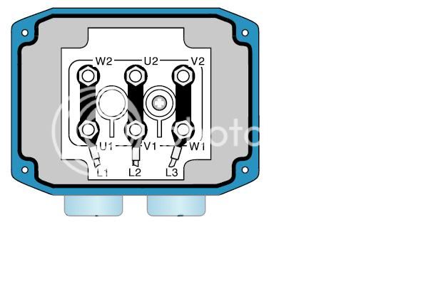
right i have a 380-420vy 1.85kw motor not sure on hp
inverter is a ac tech scf series
wired the single phase in and 3 phase out but does not work
volt meter reads 148v at each phase to ground but phase to phase 0v have i set it up wrong can anyone help
heres the manual thanks
http://www.ctiautomation.net/PDF/AC-Tech/AC-Tech-SCF-Drives-Installation-Operation-Manual.pdf

At no point in the op does it list the particular model number in question. The linked manual lists 32 different model types, of varying parameters. Until such time as we know exactly which model we are dealing with then this entire thread is full of nothing more than educated guesses. Guesses can be both dangerous and deadly.
 
bomjac, i apologise and stand corrected, but this aint rocket science, if i was asking these questions i would be sacked on the spot, but the op hasnt much motor experience so maybe i'm being complacent, 32 different types? of models ? yes, of input and outputs?? dont think so. ill hand this over to you m8, later.
 
Some questions -

  • You say you are putting in single phase ? exactly what - Single phase 230V or dual phase 400V.
  • Is the unit a single/3 phase, single phase only or 3 phase only. Which of the possible input voltage ranges is it ?
  • What is the model number of the invertor you are using ?
  • The manual provided and the model number to give you out exactly what input / output volts and frequency you need and should have.
0.75 kW = 1hp, so your motor is 2.5 HP.

Sorry to ask so many questions, but the information supplied is not enough to do anything other than take a wild guess to fill in the blanks and try to give an answer. Also unless we know the full information then acting on any response could potentially cause damage to both the equipment and more worryingly yourself or others.

surely some of your questions are answred in the op. you ask single phase or dual phase. he says single phase, and 3 phase out. maybe I can't read???. as usual there is someone who asks over the top questions rather than help.
 
If its a single phase input inverter (ie. 230vac) then you will not get 380-420v to your motor!!!

If you have a dual voltage motor, where you can use 3ph 230v D... you may be in luck.


.
 
At no point in the op does it list the particular model number in question. The linked manual lists 32 different model types, of varying parameters. Until such time as we know exactly which model we are dealing with then this entire thread is full of nothing more than educated guesses. Guesses can be both dangerous and deadly.

I'll hazard a guess at SF230Y

.
 
Just going on past experience have you got a pot or resistor connected to the speed reference? No resistance = no speed. Also where is the safety contactor fitted? If after the VFD it needs to be closed before the VFD is energised.
 
hi thanks for all you replies
all i want to do is make my 240v supply work my 3 phase motor as i think this inverter will do this job
i will get the full part number today of the scf
the motor has 2 voltage ops on it one is 380-420v Y
the other being 220-240v delta 2820 r/min 3-50hz
i asume this is what you mean if your asking if the motor is dual power thanks

thanks for all you help everyone i will let you know how it all goes tonight
 
Hi,
as you have said the motor is a dual voltage type, first, the motor needs to be wired for 220-240v delta. then you need to access the inverter program parameters to set the current limit and overload levels for the motor, this would protect the motor if any thing went a miss.
you will have to decide which stop start set up you need for your application, i personally would use two wire stop start using preset speeds,fwd and rev. i would use an accel time for starting(soft start) and coast to stop.
the strange voltage you are getting are down to the fact that the out put voltage of the inverter is DC pulsed to simulate AC.
 
hi guys i have wired the motor to each opposite terminal which being v2-w1 u2-v1
u1-w2 is this right or have i got to wire it to the terminals you said
also the inverter came in a prefab box which has on off sw and a dial for freq (but this is broken) and a reverse sw
at the moment all it is doing is buzzing wont spin thanks
 
See my last post, I asked if there was a pot on the speed reference. It’s usually 0 to 10K linier. I normally use a 10 turn wire wound. Read the rest of the post as well!
Motor connections
Delta
U1 > V2
V1 > W2
W1 > U2
Star
U1
V1
W1
U2,V2 & W2 bridged
 
Motor to be connected as:

DeltaConnection.jpg


You'll need to drill through the parameters ensuring motor base speed is 50Hz, motor voltage is correct, control is via terminal strip and speed is via potentiometer. Is this motor fitted to the ramp (ie. under load) or is it buzzing on the bench (ie. not under load)?

We're assuming your motor is new or is known to be in a fully operational condition or tested for electrical balance.

The manual is pretty decent and will be your biggest help. Any model number yet?

.
 
Last edited by a moderator:
The manufactures usually offset the connections so you can fit links in a straight line to the opposite terminal.

Top row
U1 V1 W1
Bottom row
W2 U2 V2
 
model is sf250yf-787
so i just wire strait across as pic shows

got it moving now it was down to the broken sw i just need to run it at 50 hz i assum
thanks for the help every one cheers
 
pmac10... quite rightly points out the answers were in the first 8 posts!!!

I think we're all in agreement that some trainees should leave the real jobs to the qualified sparks.

A little knowledge is effing dangerous to some!
 
Mr Foxx, on the subject of wiring motors/inverters, i have adopted a new 'best practice' at the motor terminal box. connect the CPC first. why? two minor explosions in my face from connnecting the CPC last and knipping a phase wire with the contact plate of the CPC. two ?? you say? it was a brake motor and i thought i'd ****** up the brake wiring, so had to make sure, so yes two, lol, pass it on mate;)
 
Last edited by a moderator:
hi guys just set the ramp up but the motor wont lift it the only thing i can think is i only have 145-148 v at each phase but do no how to increase it any help welcome thanks
 
Hi

is the voltage reading you are getting the inverter out put, if it is then the voltage is dependant on the speed you have set on the inverter, sounds to me that the speed is set too low, you will need to find out how to access the invertor parameters and alter speed.
The dc bus + and- may be a dc brake, does it not read dc brake + and - ? if so does not need to be connected
 
Hi

when you access the parameters check the accel and decel times , max torque and current.

the voltage to the motor from the inverter is not a true ac voltage!
 
heres what the settings ar on
lin voltage. high accel time.0.1
carrier freq .10khz dec time 0.1
start method. normal min freq 0 max freq. 60 current limit 150% i have set the pot to 50 hzs
stop method. ramp
standard speed sorce. 0-10vdc
 
justin, i know ive replied on this thread before but cant remember the details and im not reading 40 odd posts again, you say you have a 0-10V speed source, have you actually wired a potentiometer for speed control? if not, you may need to change that parameter, if the inverter is looking for a 0-10V input and one is not present it will read 0v which will correspond to your minimal speed, ie 0Hz, hence no movement, if im talking crap and overlooked something in previous posts feel free to let me know:)
 
i think thats what i have not sure as the unit was pre made by rotor motor but i assume you mean the dial that adjusts the freq and is displayed in the screen is there any way i can just set the inverter to just give me 3 phas at 50hz thanks
 
yeah youre right, most inverters can be wired for a remote pot though which was what i was thinking of, set your minimum speed to 50hz and your maximum to 51hz and increase your ramp up time to maybe 2 sec, sorry if im repeating but what make is your inverter?
 
just reread your parameters, you say youve set the pot to 50hz, what does that mean? is it possible youve set the speed source 0-10Vdc and the pot 4-20mA at 50hz??
 
thanks god its working that done the job all il have to do is pull in a 230 supply to the control circuit on the ramp it dont like running off one of the inverter phases
 
glad its working, as mentioned earlier, your inverter output is not true ac so never try to tap off it, its like a stepped square sine wave, but also you would create an imbalanced load on the output and most likely cause your inverter to trip out.
good luck.
 
Glad to see its working,should be a parameter which shows the current the motor is pulling, it would be worth while to check the current.
a clamp meter will not give an accurate reading!
 

Reply to help wiring inverter to car ramp in the Electricians' Talk | All Countries area at ElectriciansForums.net

Similar Threads

Hi All I am new on here and looking for some advice on converting a car ramp to single phase. This particular ramp is sold in 2 versions single or...
Replies
6
Views
2K
Baja wiring harness LED light help. I've fitted a US Baja harness on my Australian FJ, but I need to replace the Baja harness switch setup so...
Replies
0
Views
813
Hi guys, I am new to the forum so be nice! I used to install solar PV systems back when the tariffs were still good, and I've never had to go...
Replies
5
Views
5K
I am taking this HVAC class and have been studying up on the basics of electricity, magnetic induction, AC/DC, Ohms Law etc. I have a basic...
Replies
16
Views
9K
Hi guys Is there anyone who can help me with some information to help me get a FKI BRADBURY 20 series 2 post car lift up and running, the model...
Replies
10
Views
7K

OFFICIAL SPONSORS

Electrical Goods - Electrical Tools - Brand Names Electrician Courses Green Electrical Goods PCB Way Electrical Goods - Electrical Tools - Brand Names Pushfit Wire Connectors Electric Underfloor Heating Electrician Courses
These Official Forum Sponsors May Provide Discounts to Regular Forum Members - If you would like to sponsor us then CLICK HERE and post a thread with who you are, and we'll send you some stats etc

YOUR Unread Posts

This website was designed, optimised and is hosted by untold.media Operating under the name Untold Media since 2001.
Back
Top