E
enpassant
Hello folks, hoping for some help on a project I'm doing at home involving my 3D Printer (...it's 2019... who doesn't have one of these things at home?!)
It has a 24V 25A power supply providing the juice but it's a cheap LED driver and it's noisy - it's just the fan but as it's in the living room, it's annoying.
I've bought a new PSU to replace it with but before I hook it up I want to make sure it's not going to snap, crackle and pop! I'm looking to replace it with this silent, fan-less, Meanwell HLG-600H-24A [600W], please see:


Currently everything is connected to a common rail on the power supply (controller board, heated glass printbed via solid-state relay, 3x 24V fans, LED strip to watch it make stuff)
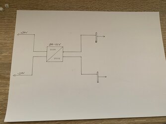
I am changing it slightly and am using some busbars to splits things up: I have +24V & -24V being supplied from the PSU and from there +12V & -12V busbars via DC-DC 24-12 converter, which I will run replace the 24V fans with 3x new 12V fans and a also new 12V LED strip. I've hooked this part up to the current PSU, please see:

The main reason for question is that the Meanwell PSU is a "single output" supply, which adds up as there's only 1x rectifier with + & - coming from, but as per the "mechanical spec" it has 2x 24V output cables and another with RC+/- & GND. I assume from the the diagram above these are simply in parallel and the RC cables I have absolutely not a clue what they're for, but since they're 5V and linked to some form of PWM control of the PSU I'll likely cut them back and ignore.
What I'm looking to do is simply connect the 2x positives to 1 busbar and the 2x negatives to the other busbar then provide the 24V stuff from there... and step-down the 12V as in the picture.
I assume, then, that it would become this:


The 3D Printer is rated as 600W peak but I don't know the exact specs for all the components. The controller board is 24V and directly supplies the DC stepper motors and the heated nozzle for melting the plastic. I don't have specs for the heated printbed but that's obviously the biggest contender for that power demand.
The output cables are 14 gauge, and a quick google gives me equivalent as 2.5mm2, but I'm not sure how accurate that is.
a. I'm unsure if each output cable would be able to take the 600W (in which case why have 2?).
b. What would the result be of joining the 2x +'s and the 2x -'s as above?
Should probably also mention the 3D Printer is >£6k and the PSU is fairly expensive, instead of the normal £30 on Amazon, it cost >£200, hence my reluctance to just plumb it in and hope for the best!
It has a 24V 25A power supply providing the juice but it's a cheap LED driver and it's noisy - it's just the fan but as it's in the living room, it's annoying.
I've bought a new PSU to replace it with but before I hook it up I want to make sure it's not going to snap, crackle and pop! I'm looking to replace it with this silent, fan-less, Meanwell HLG-600H-24A [600W], please see:
Currently everything is connected to a common rail on the power supply (controller board, heated glass printbed via solid-state relay, 3x 24V fans, LED strip to watch it make stuff)
I am changing it slightly and am using some busbars to splits things up: I have +24V & -24V being supplied from the PSU and from there +12V & -12V busbars via DC-DC 24-12 converter, which I will run replace the 24V fans with 3x new 12V fans and a also new 12V LED strip. I've hooked this part up to the current PSU, please see:
The main reason for question is that the Meanwell PSU is a "single output" supply, which adds up as there's only 1x rectifier with + & - coming from, but as per the "mechanical spec" it has 2x 24V output cables and another with RC+/- & GND. I assume from the the diagram above these are simply in parallel and the RC cables I have absolutely not a clue what they're for, but since they're 5V and linked to some form of PWM control of the PSU I'll likely cut them back and ignore.
What I'm looking to do is simply connect the 2x positives to 1 busbar and the 2x negatives to the other busbar then provide the 24V stuff from there... and step-down the 12V as in the picture.
I assume, then, that it would become this:
The 3D Printer is rated as 600W peak but I don't know the exact specs for all the components. The controller board is 24V and directly supplies the DC stepper motors and the heated nozzle for melting the plastic. I don't have specs for the heated printbed but that's obviously the biggest contender for that power demand.
The output cables are 14 gauge, and a quick google gives me equivalent as 2.5mm2, but I'm not sure how accurate that is.
a. I'm unsure if each output cable would be able to take the 600W (in which case why have 2?).
b. What would the result be of joining the 2x +'s and the 2x -'s as above?
Should probably also mention the 3D Printer is >£6k and the PSU is fairly expensive, instead of the normal £30 on Amazon, it cost >£200, hence my reluctance to just plumb it in and hope for the best!