J
jezzurp
Hi all
I haven’t done much of anything with electrics since secondary school (long time) and hoping someone might just double check what I’m saying isn’t totally wrong!
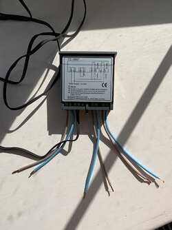
Im building a keg system for home brew using an old chest feeezer. To regulate the temperature I’m using an ink bird ITC 1000 temperature controller. I will attach some pics to illustrate what I’m talking about but essentially I’m chopping up a couple of 2 way adaptors and the plan is...
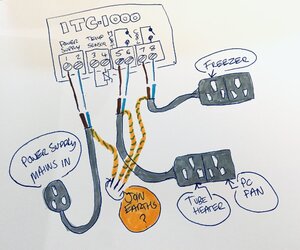
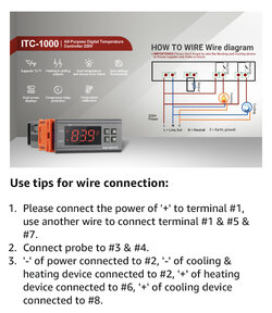
Mains supply comes in through small hole in freezer, I wire up live and neutral to relevant terminals (1 & 2) for power supply.
Temperature sensor is wired to terminals 3 & 4.
There are then two outputs.
One two way adaptors live and neutral are wired into terminals 5 & 6 for the heating output (little tube heater and pc fan to circulate)
The other two way adaptor live and neutral wired to ports 7 & 8 for cooling output (will feed freezer plug in to it).
I have watched lots of videos and read up abs from what I understand I should combine the earth wires from the three power cables (mains supply, hot and cold outputs to adaptors) and solder and cap off. As I’m not super sure about electrics I thought I should check with people who know before I plough ahead and blow myself up, or worse still waste beer!
Any help much appreciated. Thanks
I haven’t done much of anything with electrics since secondary school (long time) and hoping someone might just double check what I’m saying isn’t totally wrong!
Im building a keg system for home brew using an old chest feeezer. To regulate the temperature I’m using an ink bird ITC 1000 temperature controller. I will attach some pics to illustrate what I’m talking about but essentially I’m chopping up a couple of 2 way adaptors and the plan is...
Mains supply comes in through small hole in freezer, I wire up live and neutral to relevant terminals (1 & 2) for power supply.
Temperature sensor is wired to terminals 3 & 4.
There are then two outputs.
One two way adaptors live and neutral are wired into terminals 5 & 6 for the heating output (little tube heater and pc fan to circulate)
The other two way adaptor live and neutral wired to ports 7 & 8 for cooling output (will feed freezer plug in to it).
I have watched lots of videos and read up abs from what I understand I should combine the earth wires from the three power cables (mains supply, hot and cold outputs to adaptors) and solder and cap off. As I’m not super sure about electrics I thought I should check with people who know before I plough ahead and blow myself up, or worse still waste beer!
Any help much appreciated. Thanks