Discuss TV Lift Reverse Polarity Motor and Limit Switches perhaps? in the UK Electrical Forum area at ElectriciansForums.net

Reaction score
0
Hi.
I want to control a TV Lift from a home automation system. Its hasn't got any standard way of doing this and the person setting the home automation needs to know just a few things to get it working.

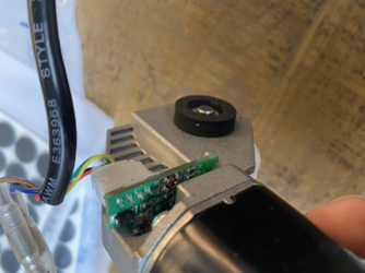
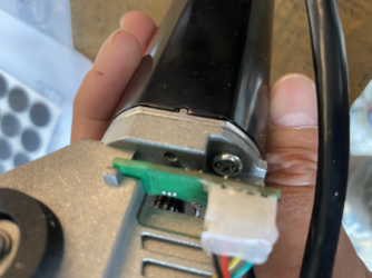
Ive had an electrician look at the control box and motor, he's figured out that the control box sends power to the motor for up and reverses the polarity for down, brown/blue. There are then 4 more wires coming from the motor to the control box and he thought that they must be the limit switches that shorts to stops the motor going up or down, but he couldn't find a correct short, they were all over the place.

Ive attached a photo of the motor and wires attached... any help would be very gratefully received ... here's hoping.
 

Attachments

  • tempImagetWWUOM.png
    3.5 MB · Views: 18
  • tempImagekhKMKb.png
    3.4 MB · Views: 18
I would say they are not limit switches, but what you have is in fact a rotary encoder... similar to those found in the original computer mice (the one's with a rubber covered ball that rotated against rollers).

With two opto-transistors, detecting the rising/falling edges of them allows you to determine which direction the rotation is going in (in one direction, say signal 1 will lead signal 2, in the other signal 2 leads) and how much it's rotating (counting the pules).

Four wires is enough... and this is just an example... 0v and +5v for IR LEDs and two signals back from the transistors.

What you need is an oscilloscope to watch the signals as the drive is running. This would allow you to count pulses per revolution and determine which leads for each direction of rotation.
 
Brilliant, thanks so much for your help on this, I’ve had two people look at it already.

The system we are installing is capable of running the power and reversing the polarity, what he needs is a stop signal at the top and the bottom. If I can pick up oscilloscope, what exactly do I look for?
 
Just to be clear... I'm assuming this is what that board is... I could be wrong... but if it is a simple rotary encoder, you'll be getting two signals out of it. To complicate it, the lines could be sourcing a signal (in this case, they may be switching between say 0v and 5v) or they could be sinking a signal. Sinking is a little trickier to look for, especially if the other end is not connected to the controller because when you sink a signal you may pull the line high to say 5v using a relatively high value resistor.... when the transistor is exposed to light, it basically connects the line to 0v or vice versa.

My advice would be to get the model/part no. off the drive or the PCB and go looking for a data sheet for it.

All that aside, if it works as I've outlined above, you may get something like this....

S1 _ _ _ - _ _ _ - _ _ _ -
S2 _ _ - _ _ _ - _ _ _ - _

When the shaft is rotating in one direction and...

S1 _ _ - _ _ _ - _ _ _ - _
S2 _ _ _ - _ _ _ - _ _ _ -

When it's rotating in the other direction.

Determining the position requires you count the pulses and look at the direction to establish a position value. Say an integer in the range 0 to 65536 where 0 is the bottom and 65536 is the top. The issue you have is that if you get a power interruption during operation, unless you write your position data to some form of static RAM chip (I'm thinking you're going to need some form of microcontroller to do this) for every change (writing to static RAM can be costly in terms of time and you may not be able to keep up) you would also need to include some form of limit switch for say the bottom of travel... when the power comes on, you wind down until you hit the limit and then reset your counter so you have a known position from which to start. Over time, these systems are likely to drift if you don't reset to a known location periodically... all it takes is a missed pulse here and there and depending on the lift mechanism (I'm assuming probably some kind of screw thread) and you could be a few mm out each time.

The other thing to consider here is safety. The power of that motor will be such that you should probably consider some form of interlock that prevents operation if objects are detected in a certain area. The safety angle is something that would probably make me not even consider taking on something like this if you end up needed professional help.

Fundamentally though this is basic robotics, something I suspect an Arduino could handle and I'm pretty certain you could find lots of information if you start somewhere like AdaFruit as they have a shed load of tutorials etc.

In all honesty, I might be inclined to go super simple and use basic relays and mechanical limit switches rather than even consider using that encoder, just for the simplicity and reliability but then I don't know where it's going to be installed/enclosed.
 
I agree with @SparkyChick that it is probably an incremental encoder, as it appears to be on the input shaft of the gearbox so it would do multiple rotations for an output turn (so simple limits not likely to be there).

Most professional incremental encoders have an index/origin pulse to get the start point, but if geared down you really need some means of knowing a specific location on the output shaft to get your known location.

It might even be simpler to look at some absolute encoder systems, from a simple potentiometer to one of the encoders that had the equivalent of a grey code or whatever internally so even from a reboot/cold start you know where it is.

In all cases you should have limit switches as you should never have a single point of failure in anything that can break itself or something/someone important! In fact, if it has any real risk of that you ought to be doing a detailed risk-assessment before going through the design requierments.
I went back with the other suggestion to my installer and he thinks using the mechanical limits as a failsafe is the way to go and just to solder wires to the up and down buttons and he can simulate the button push ….
 

Reply to TV Lift Reverse Polarity Motor and Limit Switches perhaps? in the UK Electrical Forum area at ElectriciansForums.net

Similar Threads

Hello, I wired a DPDT switch to my sunroof 12v DC motor. It was working ok and I was able to reverse the polarity of the motor to open and close...
Replies
3
Views
753
Hi guys, Been given a motor and associated control gear within a panel that has been water damaged. This motor has 3 windings U1/U2, V1/V2 and...
Replies
2
Views
1K
I posted a month ago regarding a single phase motor + panel I have been given to try and sort following water damage to the panel. The assembly...
Replies
0
Views
1K
Installed a new ceiling fan, with no previous light or power. There is a switch in the room that controls an outlet. I am trying to draw power...
Replies
0
Views
740
I need some advice on how to wire this motor please! Its for a large clothing conveyor . 120 volt power . Its an instant reversing motor...
Replies
1
Views
665

OFFICIAL SPONSORS

Electrical Goods - Electrical Tools - Brand Names Electrician Courses Green Electrical Goods PCB Way Electrical Goods - Electrical Tools - Brand Names Pushfit Wire Connectors Electric Underfloor Heating Electrician Courses
These Official Forum Sponsors May Provide Discounts to Regular Forum Members - If you would like to sponsor us then CLICK HERE and post a thread with who you are, and we'll send you some stats etc

Electrical Forum

Welcome to the Electrical Forum at ElectriciansForums.net. The friendliest electrical forum online. General electrical questions and answers can be found in the electrical forum.
This website was designed, optimised and is hosted by Untold Media. Operating under the name Untold Media since 2001.
Back
Top
AdBlock Detected

We get it, advertisements are annoying!

Sure, ad-blocking software does a great job at blocking ads, but it also blocks useful features of our website. For the best site experience please disable your AdBlocker.

I've Disabled AdBlock