Apr 14, 2023
31
6
83
UK
If you're a qualified, trainee, or retired electrician - Which country is it that your work will be / is / was aimed at?
United Kingdom
What type of forum member are you?
Practising Electrician (Qualified - Domestic or Commercial etc)
Hi Guys,

Had a call out today about an odd issue with a newish Creda DT storage heater.

Basically..

Storage heaters were installed in one flat and connected to two separate CU's each with RCBO proptection and were working perfectly.

These were then removed and installed in a flat in the same block, and this time, 24hr supply is connected to a new CU with RCBO, and (for some reason) OP side connected to an old rewireable CU that was not changed.

Problem is, whenever the OP isolator is switched on ready for charge, it instantly trips the 24 RCBO.

After doing a bit more investigating, it turns out the 24hr supply is back feeding up the OP side. Each set of terminals on the main circuit board seem to be permanently connected which is causing the RCBO to trip due the the two neutrals being 'connected' in the heater. Also, the heater elements are engergised via the 24hr supply as well which cant be right?

So, there was still an unused heater in their store room so i swapped out the circuit board from that unused one and it still had the same issue.

Its a Creda FWIW.

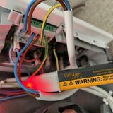
Ill attach some pics


The Dimplex version can be wired for 'single supply' which involves moving a brown live and a blue neutral jumper wire onto different spade tabs, that then provides power to the off peak terminals when there is only a 24 hour supply. The charging times are then programmed in the settings to match the off peak times.

The Creda manual seems to suggest it is only suitable for dual supplies though.

I assume you have checked the internal wiring for damage and correct connections, the 2 upper elements are fed form OP and the bottom is fed from 24hour. It would be possible to mix up the wiring at the elements or stats, but these would not normally be unplugged. Were the elements removed during dismantling?

Your photo doesn't show the PCB well but if it is the same as the Dimplex version, the blue link wire at the top is joining the OP and 24h neutral supplies together, I cant see what the brown link is doing, but from photos I have it looks as if it is joining the OP and 24h live supplies.
No from what i can see all the internal wiring is all intact although i did have another picture and found this..


SO i assume i need to remove these links although they do look factory fitted!

Also just spotted in the manual on Page 10 that it states not suitable for single supplies.


Their technical support people have been monumentally useless as nobody seems to want to return phone calls!
 
Last edited:
The PCB certainly appears to be the same. Those 4 tabs are used to connect to a remote terminal block in the Dimplex version, rather than the small block soldered onto the PCB in the Creda version. The top 3 tabs are Neutral 24hour, Neutral OP, Live 24hour and the one below the grey capacitor is Live OP. Those links certainly appear to link the 2 supplies together. It certainly does look original though.

Do the working heaters have the links fitted?

I've attached a photo of Quantum heater PCB which shows the 4 tabs going to 4 separate terminals.

To make the quantum heaters single supply, the looped wires currently parked in the top 2 terminals are connected to the spades on the bottom 2 terminals to provide power to both pairs all the time. Doing so would be the same configuration in your photo. Note the brown link has been cut off for some reason in this heater. This heater was totally incorrectly installed as were all the others at the property which was why I was at the property. But it clearly shows what tab is connected to what supply cable.

Quantum PCB.jpg


Edit, I've just found a photo of a replacement Creda PCB for sale, it shows the links have piggyback terminals and are not linked to anything, but plugged together. If you put the links back as the Creda photo (or just remove them altogether) it should all be good again.
creda.jpg
 
The PCB certainly appears to be the same. Those 4 tabs are used to connect to a remote terminal block in the Dimplex version, rather than the small block soldered onto the PCB in the Creda version. The top 3 tabs are Neutral 24hour, Neutral OP, Live 24hour and the one below the grey capacitor is Live OP. Those links certainly appear to link the 2 supplies together. It certainly does look original though.

Do the working heaters have the links fitted?

I've attached a photo of Quantum heater PCB which shows the 4 tabs going to 4 separate terminals.

To make the quantum heaters single supply, the looped wires currently parked in the top 2 terminals are connected to the spades on the bottom 2 terminals to provide power to both pairs all the time. Doing so would be the same configuration in your photo. Note the brown link has been cut off for some reason in this heater. This heater was totally incorrectly installed as were all the others at the property which was why I was at the property. But it clearly shows what tab is connected to what supply cable.

View attachment 112145

Edit, I've just found a photo of a replacement Creda PCB for sale, it shows the links have piggyback terminals and are not linked to anything, but plugged together. If you put the links back as the Creda photo (or just remove them altogether) it should all be good again.
View attachment 112146
Fantastic thanks Freddo that last photo confirms all your suggestions so I’ll get back over and remove the links and test.

Thanks again!
 
  • Like
Reactions: freddo

Similar threads

OFFICIAL SPONSORS

Electrical Goods - Electrical Tools - Brand Names Electrician Courses Green Electrical Goods PCB Way Electric Underfloor Heating Electrician Courses Heating 2 Go Electrician Workwear Supplier
These Official Forum Sponsors May Provide Discounts to Regular Forum Members - If you would like to sponsor us then CLICK HERE and post a thread with who you are, and we'll send you some stats etc

Advert

Daily, weekly or monthly email

Thread starter

Joined
Location
UK
If you're a qualified, trainee, or retired electrician - Which country is it that your work will be / is / was aimed at?
United Kingdom
What type of forum member are you?
Practising Electrician (Qualified - Domestic or Commercial etc)

Thread Information

Title
Storage Heater Issue
Prefix
N/A
Forum
UK Electrical Forum
Start date
Last reply date
Replies
4

Advert

Thread statistics

Created
Initforthemoney,
Last reply from
Initforthemoney,
Replies
4
Views
1,371

Advert