Discuss Calculating inrush current for magnetic ballasts in the UK Electrical Forum area at ElectriciansForums.net

davesparks

-
Mentor
Esteemed
Arms
Reaction score
17,062
I need to, as accurately as possible, establish what the inrush current is for some large metal halide floodlights with magnetic ballasts and I'm drawing a blank.

This is for a switchgear/DB replacement I am in the planning stages of and need to know whether these circuits can be fed from MCBs or if I need to use MCCBs or if fuses would be OK.
These are currently fed from 63A MCCBs, but it would be advantageous if they could be run on MCB's instead.

There are 4 TP circuits each feeding a floodlight column. Each column has 9x 2kW MBIL type discharge lamps on it with magnetic ballasts connected in delta with loads evenly distributed (3 connected between L1 and L2, 3 between L2 and L3 and 3 between L1 and L3).

I've tried asking schneider as they can usually look up a maximum number of fittings for a given MCB, but they dont have info for this size fitting and can't help without the inrush data.

So I've asked the ballast manufacturer, Thorn, for the inrush data and they apparently don't know. But they did come up with a max starting current (not inrush) of 9.3A at 415V.

Can anybody help with calculating the inrush for these?
 
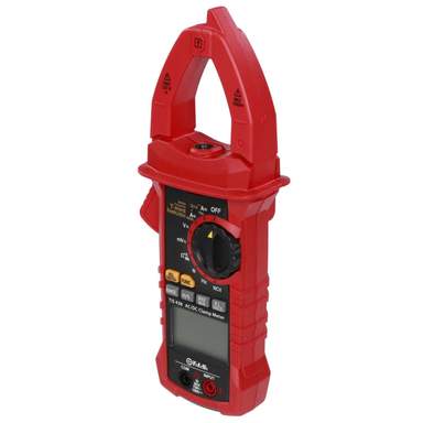
Can you use a meter to measure it, a flexible probe or clamp device?
I think these are specialist devices but maybe available for rental.
 
Last edited:
Can you use a meter to measure it, a flexible probe or clamp device?
I think these are specialist devices but maybe available for rental.

I'm going to see what the clamp meter says tomorrow, I doubt it reacts fast enough to record the inrush though.

Yes measuring it would be the logical and most accurate answer, but it will require the right testers, which I don't have. Hiring is an option but the motivation here is to get the job into a shoestring budget.
I have a fluke 360 clamp meter, it reacts quick enough to measure the inrush current as long as your quick enough to press hold you'll get a reading. Its out of production now but the newer version is usually available to hire.
 
Trouble is digital meters just aren’t fast enough for this, How about an analogue meter like an Avo8 connected to a small split core CT? Say 200:5 ratio? With an analogue meter you should be able to see the inrush.
 
Trouble is digital meters just aren’t fast enough for this, How about an analogue meter like an Avo8 connected to a small split core CT? Say 200:5 ratio? With an analogue meter you should be able to see the inrush.

You should be able to see it, but I can't guarantee to be able to read it quick enough!

Sadly this also comes back to not having the right test equipment available, I know where I could lay my hands on an AVO8 easy enough, but don't think I could find a split CT.
 
I seem to remember the measuring gear is specific,with peak and graph data. I also think you can do three tests,and get three different readings :)

This was SP switchgear,and solving was sometimes a mixture of calculating,and trial/error,usually SB fuses or current limiting devices.
 
I seem to remember the measuring gear is specific,with peak and graph data. I also think you can do three tests,and get three different readings :)

Oh yeah, that's the other issue witheasuring it, the inrush depends on whereabouts the volkatge is in its cycle when it is turned on.

It's an inductor so, Iirc, if it switches on at the zero point the inrush is at its greatest and if it switches on when the voltage is at its peak there won't be an inrush.

But then this is a three phase load so it can't exactly be switched on at zero or peak.

The longer I spend trying to resolve this the more I am inclined to leave the old rusty panel with VIR incomers in place and run away.
 
I was actually repairing some Thorn 2KW MBILs last night! Cartridge fuses will naturally cope with the inrush of almost all circuits. Where I was working have groups of 8 2KW lamps switched on at a time, these are fed from standard Merlin MCBs, though unhelpfully I can't remember the type or rating...
 
I was actually repairing some Thorn 2KW MBILs last night! Cartridge fuses will naturally cope with the inrush of almost all circuits. Where I was working have groups of 8 2KW lamps switched on at a time, these are fed from standard Merlin MCBs, though unhelpfully I can't remember the type or rating...

Were they single or three phase circuits?

Is that 8 lamps on one MCB?


Each individual lamp on my site has an MCB, though they are all random sizes and types ranging from B16 to D20.

Each bank of 9 is on one circuit which is protected at 63A by an MCCB currently.
 
8 lamps (415V) on one 3 phase MCB, the lights are balanced as well as you can balance 8 lights across 3 phases. The MCBs for each light are 2 pole 16amp some are B type others C type.
 
8 lamps (415V) on one 3 phase MCB, the lights are balanced as well as you can balance 8 lights across 3 phases. The MCBs for each light are 2 pole 16amp some are B type others C type.

I assume they are normal MCB's not the physically bigger C120 range?

If that installation doesn't have any issues with nuisance tripping then I can't see 9 being any different.
 
Just the usual C60 range.

I agree. The install was put in ~20 years ago and hasn't had any nuisance tripping.

That makes me think we should be fine on C60 MCB's here then. The circuits feeding the columns should be good for a 63A D type once we've completed remedials for the poor earthing, I'll know more once I have the new Zs readings tomorrow.

These floodlights are around 25 years old.
 
See first table in which makes recommendations on ratings and types of CB and contactors:

https://www.veelite.com/wp-content/uploads/Protection-of-Lamp-Circuits3.pdf

I will see if I can find anything else.
[automerge]1597809686[/automerge]
See page 4 of:

http://www.moeller.net/binary/ver_techpapers/ver955en.pdf

and see table in which has starting surge current and its typical duration:

Discharge lamps - Electrical Installation Guide - https://www.electrical-installation.org/enwiki/Discharge_lamps
 
Last edited:
I too would test on site, but using a scope and a shunt or CT. There's nothing like seeing a picture of it to get a proper feel for what is going on.
There are three separate causes of inrush here:
PFC capacitor charging: less than half a cycle, instantaneous current could approach PSCC for a time constant of Zs x C. Worst when contacts close just before V=Vpk
Magnetic saturation: Worst when contacts close at V=0 since this causes the greatest magnetic excursion. Instantaneous current could approach V/(Zs+Rwindings). Duration usually a few cycles while the core gets into step with the mains.
Starting current: Lower, longer, depends on lamp and well documented by the lamp makers.

Watching the waveform would reveal each of these components and allow a good estimation of the I²t that the breaker has to put up with.
Took the words right out of my mouth ?
 

Reply to Calculating inrush current for magnetic ballasts in the UK Electrical Forum area at ElectriciansForums.net

Similar Threads

I am upgrading garage lighting. I have installed 12 40W batten lights (cheap Amazon variety - don’t have specs). 6A breaker in Garage consumer...
Replies
16
Views
2K
When I joined this forum a decade or so back, there was a discussion going on about a welder that was connected with a 3-core cable to L1, L2 and...
Replies
3
Views
2K
Hi, I have a Victron Multiplus-II 5kVA inverter/charger with Pylontech US5000 batteries installed in my house along with a 6.8kWp PV array and...
Replies
12
Views
425
Sorry for the long first post, I wanted to be as thorough as possible. On my landing I have a 2-way switch setup, one of which is 3-gang, one of...
Replies
5
Views
2K
Evening all.. A friend/customer has just asked if I could connect up this commercial washing machine down at his domestic stables. He has had it...
Replies
9
Views
1K

OFFICIAL SPONSORS

Electrical Goods - Electrical Tools - Brand Names Electrician Courses Green Electrical Goods PCB Way Electrical Goods - Electrical Tools - Brand Names Pushfit Wire Connectors Electric Underfloor Heating Electrician Courses
These Official Forum Sponsors May Provide Discounts to Regular Forum Members - If you would like to sponsor us then CLICK HERE and post a thread with who you are, and we'll send you some stats etc

Electrical Forum

Welcome to the Electrical Forum at ElectriciansForums.net. The friendliest electrical forum online. General electrical questions and answers can be found in the electrical forum.
This website was designed, optimised and is hosted by Untold Media. Operating under the name Untold Media since 2001.
Back
Top
AdBlock Detected

We get it, advertisements are annoying!

Sure, ad-blocking software does a great job at blocking ads, but it also blocks useful features of our website. For the best site experience please disable your AdBlocker.

I've Disabled AdBlock